Category Archives: Fragmentarium

Path Tracing 3D Fractals

In some ways path tracing is one of the simplest and most intuitive ways to do ray tracing.

Imagine you want to simulate how the photons from one or more light sources bounce around a scene before reaching a camera. Each time a photon hits a surface, we choose a new randomly reflected direction and continue, adjusting the intensity according to how likely the chosen reflection is. Though this approach works, only a very tiny fraction of paths would terminate at the camera.

So instead, we might start from the camera and trace the ray from here and until we hit a light source. And, if the light source is large and slowly varying (for instance when using Image Based Lighting), this may provide good results.

But if the light source is small, e.g. like the sun, we have the same problem: the chance that we hit a light source using a path of random reflections is very low, and our image will be very noisy and slowly converging. There are ways around this: one way is to trace rays starting from both the camera and the lights, and connect them (bidirectional path tracing), another is to test for possible direct lighting at each surface intersection (this is sometimes called ‘next event estimation’).

Even though the concept of path tracing might be simple, introductions to path tracing often get very mathematical. This blog post is an attempt to introduce path tracing as an operational tool without going through too many formal definitions. The examples are built around Fragmentarium (and thus GLSL) snippets, but the discussion should be quite general.

Let us start by considering how light behaves when hitting a very simple material: a perfect diffuse material.

Diffuse reflections

A Lambertian material is an ideal diffuse material, which has the same radiance when viewed from any angle.

Imagine that a Lambertian surface is hit by a light source. Consider the image above, showing some photons hitting a patch of a surface. By pure geometrical reasoning, we can see that the amount of light that hits this patch of the surface will be proportional to the cosine of the angle between the surface normal and the light ray:

\(
cos(\theta)=\vec{n} \cdot \vec{l}
\)
 
By definition of a Lambertian material this amount of incoming light will then be reflected with the same probability in all directions.

Now, to find the total light intensity in a given (outgoing) direction, we need to integrate over all possible incoming directions in the hemisphere:

\(
L_{out}(\vec\omega_o) = \int K*L_{in}(\vec\omega_i)cos(\theta)d\vec\omega_i
\)
 
where K is a constant that determines how much of the incoming light is absorbed in the material, and how much is reflected. Notice, that there must be an upper bound to the value of K – too high a value would mean we emitted more light than we received. This is referred to as the ‘conservation of energy’ constraint, which puts the following bound on K:

\(
\int Kcos(\theta)d\vec\omega_i \leq 1
\)
 
Since K is a constant, this integral is easy to solve (see e.g. equation 30 here):

\(
K \leq 1/\pi
\)
 
Instead of using the constant K, when talking about a diffuse materials reflectivity, it is common to use the Albedo, defined as \( Albedo = K\pi \). The Albedo is thus always between 0 and 1 for a physical diffuse materials. Using the Albedo definition, we have:

\(
L_{out}(\vec\omega_o) = \int (Albedo/\pi)*L_{in}(\vec\omega_i)cos(\theta)d\vec\omega_i
\)
 
The above is the Rendering Equation for a diffuse material. It describes how light scatters at a single point. Our diffuse material is a special case of the more general formula:

\(
L_{out}(\vec\omega_o) = \int BRDF(\vec\omega_i,\vec\omega_o)*L_{in}(\vec\omega_i)cos(\theta)d\vec\omega_i
\)
 
Where the BRDF (Bidirectional Reflectance Distribution Function) is a function that describes the reflection properties of the given material: i.e. do we have a shiny, metallic surface or a diffuse material.


Completely diffuse material (click for large version)

How to solve the rendering equation

An integral is a continuous quantity, which we must turn into something discrete before we can handle it on the computer.

To evaluate the integral, we will use Monte Carlo sampling, which is a very simple: to provide an estimate for an integral, we will take a number of samples and use the average values of these samples multiplied by the integration interval length.

\(
\int_a^b f(x)dx \approx \frac{b-a}{N}\sum _{i=1}^N f(X_i)
\)
 
If we apply this to our diffuse rendering equation above, we get the following discrete summation:

\(
\begin{align}
L_{out}(\vec\omega_o) &= \int (Albedo/\pi)*L_{in}(\vec\omega_i)cos(\theta)d\vec\omega_i \\
& = \frac{2\pi}{N}\sum_{\vec\omega_i} (\frac{Albedo}{\pi}) L_{in}(\vec\omega_i) (\vec{n} \cdot \vec\omega_i) \\
& = \frac{2 Albedo}{N}\sum_{\vec\omega_i} L_{in}(\vec\omega_i) (\vec{n} \cdot \vec\omega_i)
\end{align}
\)


Test render (click for large version)

Building a path tracer (in GLSL)

Now we are able to build a simple path tracer for diffuse materials. All we need to do is to shoot rays starting from the camera, and when a ray hits a surface, we will choose a random direction in the hemisphere defined by the surface normal. We will continue with this until we hit a light source. Each time the ray changes direction, we will modulate the light intensity by the factor found above:

\(
2*Color*Albedo*L_{in}(\vec\omega_i) (\vec{n} \cdot \vec\omega_i)
\)
 
The idea is to repeat this many times for each pixel, and then average the samples. This is why the sum and the division by N is no longer present in the formula. Also notice, that we have added a (material specific) color. Until now we have assumed that our materials handled all wavelengths the same way, but of course some materials absorb some wavelengths, while reflecting others. We will describe this using a three-component material color, which will modulate the light ray at each surface intersection.

All of this boils down to very few lines of codes:

vec3 color(vec3 from, vec3 dir)
{
  vec3 hit = vec3(0.0);
  vec3 hitNormal = vec3(0.0);
	
  vec3 luminance = vec3(1.0);
  for (int i=0; i < RayDepth; i++) {
    if (trace(from,dir,hit,hitNormal)) {
       dir = getSample(hitNormal); // new direction (towards light)
       luminance *= getColor()*2.0*Albedo*dot(dir,hitNormal);
       from = hit + hitNormal*minDist*2.0; // new start point
    } else {
       return luminance * getBackground( dir );
    }
  }
  return vec3(0.0); // Ray never reached a light source
}

The getBackground() method simulates the light sources in a given direction (i.e. infinitely far away). As we will see below, this fits nicely together with using Image Based Lighting.

But even when implementing getBackground() as a simple function returning a constant white color, we can get very nice images:

and

The above images were lightened only a constant white dome light, which gives the pure ambient occlusion like renders seen above.

Sampling the hemisphere in GLSL

The code above calls a 'getSample' function to sample the hemisphere.

       dir = getSample(hitNormal); // new direction (towards light)

This can be a bit tricky. There is a nice formula for \(cos^n\) sampling of a hemisphere in the GI compendium (equation 36), but you still need to align the hemisphere with the surface normal. And you need to be able to draw uniform random numbers in GLSL, which is not easy.

Below I use the standard approach of putting a seed into a noisy function. The seed should depend on the pixel coordinate and the sample number. Here is some example code:

vec2 seed = viewCoord*(float(subframe)+1.0);

vec2 rand2n() {
    seed+=vec2(-1,1);
	// implementation based on: lumina.sourceforge.net/Tutorials/Noise.html
    return vec2(fract(sin(dot(seed.xy ,vec2(12.9898,78.233))) * 43758.5453),
		fract(cos(dot(seed.xy ,vec2(4.898,7.23))) * 23421.631));
};

vec3 ortho(vec3 v) {
    //  See : http://lolengine.net/blog/2013/09/21/picking-orthogonal-vector-combing-coconuts
    return abs(v.x) > abs(v.z) ? vec3(-v.y, v.x, 0.0)  : vec3(0.0, -v.z, v.y);
}

vec3 getSampleBiased(vec3  dir, float power) {
	dir = normalize(dir);
	vec3 o1 = normalize(ortho(dir));
	vec3 o2 = normalize(cross(dir, o1));
	vec2 r = rand2n();
	r.x=r.x*2.*PI;
	r.y=pow(r.y,1.0/(power+1.0));
	float oneminus = sqrt(1.0-r.y*r.y);
	return cos(r.x)*oneminus*o1+sin(r.x)*oneminus*o2+r.y*dir;
}

vec3 getSample(vec3 dir) {
	return getSampleBiased(dir,0.0); // <- unbiased!
}

vec3 getCosineWeightedSample(vec3 dir) {
	return getSampleBiased(dir,1.0);
}

Importance Sampling

Now there are some tricks to improve the rendering a bit: Looking at the formulas above, it is clear that light sources in the surface normal direction will contribute the most to the final intensity (because of the \( \vec{n} \cdot \vec\omega_i \) term).

This means we might want sample more in the surface normal directions, since these contributions will have a bigger impact on the final average. But wait: we are estimating an integral using Monte Carlo sampling. If we bias the samples towards the higher values, surely our estimate will be too large. It turns out there is a way around that: it is okay to sample using a non-uniform distribution, as long as we divide the sample value by the probability density function (PDF).

Since we know the diffuse term is modulated by the \( \vec{n} \cdot \vec\omega_i = cos(\theta) \), it makes sense to sample from a non-uniform cosine weighted distribution. According to GI compendium (equation 35), this distribution has a PDF of \( cos(\theta) / \pi \), which we must divide by, when using cosine weighted sampling. In comparison, the uniform sampling on the hemisphere we used above, can be thought of either to be multiplied by the integral interval length (\( 2\pi \)), or diving by a constant PDF of \( 1 / 2\pi \).

If we insert this, we end up with a simpler expression for the cosine weighted sampling, since the cosine terms cancel out:

vec3 color(vec3 from, vec3 dir)
{
  vec3 hit = vec3(0.0);
  vec3 hitNormal = vec3(0.0);
	
  vec3 luminance = vec3(1.0);
  for (int i=0; i < RayDepth; i++) {
    if (trace(from,dir,hit,hitNormal)) {
       dir =getCosineWeightedSample(hitNormal);
       luminance *= getColor()*Albedo;
       from = hit + hitNormal*minDist*2.0; // new start point
    } else {
       return luminance * getBackground( dir );
    }
  }
  return vec3(0.0); // Ray never reached a light source
}

Image Based Lighting

It is now trivial to replace the constant dome light, with Image Based Lighting: just lookup the lighting from a panoramic HDR image in the 'getBackground(dir)' function.

This works nicely, at least if the environment map is not varying too much in light intensity. Here is an example:


Stereographic 4D Quaternion system (click for large version)

If, however, the environment has small, strong light sources (such as a sun), the path tracing will converge very slowly, since we are not likely to hit these by chance. But for some IBL images this works nicely - I usually use a filtered (blurred) image for lighting, since this will reduce noise a lot (though the result is not physically correct). The sIBL archive has many great free HDR images (the ones named '*_env.hdr' are prefiltered and useful for lighting).

Direct Lighting / Next Event Estimation

But without strong, localized light sources, there will be no cast shadows - only ambient occlusion like contact shadows. So how do we handle strong lights?


Test scene with IBL lighting

Let us consider the sun for a moment.

The sun has an angular diameter of 32 arc minutes, or roughly 0.5 degrees. How much of the hemisphere is this? The solid angle (which corresponds to the area covered of a unit sphere) is given by:

\(
\Omega = 2\pi (1 - \cos {\theta} )
\)
 
where \( \theta \) is half the angular diameter. Using this we get that the sun covers roughly \( 6*10^{-5} \) steradians or around 1/100000 of the hemisphere surface. You would actually need around 70000 samples, before there is even a 50% chance of a pixel actually catching some sun light (using \( 1-(1-10^{-5})^{70000} \approx 50\% \)).


Test scene: naive path tracing of a sun like light source (10000 samples per pixel!)

Obviously, we need to bias the sampling towards the important light sources in the scene - similar to what we did earlier, when we biased the sampling to follow the BRDF distribution.

One way to do this, is Direct Lighting or Next Event Estimation sampling. This is a simple extension: instead of tracing the light ray until we hit a light source, we send out a test ray in the direction of the sun light source at each surface intersection.


Test scene with direct lighting (100 samples per pixel)

Here is some example code:

vec3 getConeSample(vec3 dir, float extent) {
        // Formula 34 in GI Compendium
	dir = normalize(dir);
	vec3 o1 = normalize(ortho(dir));
	vec3 o2 = normalize(cross(dir, o1));
	vec2 r =  rand2n();
	r.x=r.x*2.*PI;
	r.y=1.0-r.y*extent;
	float oneminus = sqrt(1.0-r.y*r.y);
	return cos(r.x)*oneminus*o1+sin(r.x)*oneminus*o2+r.y*dir;
}

vec3 color(vec3 from, vec3 dir)
{
  vec3 hit = vec3(0.0);
  vec3 direct = vec3(0.0);
  vec3 hitNormal = vec3(0.0);
	
  vec3 luminance = vec3(1.0);
  for (int i=0; i < RayDepth; i++) {
    if (trace(from,dir,hit,hitNormal)) {
       dir =getCosineWeightedSample(hitNormal);
       luminance *= getColor()*Albedo;
       from = hit + hitNormal*minDist*2.0; // new start point

       // Direct lighting
       vec3 sunSampleDir = getConeSample(sunDirection,1E-5);
       float sunLight = dot(hitNormal, sunSampleDir);
       if (sunLight>0.0 && !trace(hit + hitNormal*2.0*minDist,sunSampleDir)) {
           direct += luminance*sunLight*1E-5;
       }
    } else {
       return direct + luminance*getBackground( dir );
    }
  }
  return vec3(0.0); // Ray never reached a light source
}

The 1E-5 factor is the hemisphere area covered by the sun. Notice, that you might run into precision errors with the single-precision floats used in GLSL when doing these calculations. For instance, on my graphics card, cos(0.4753 degrees) is exactly equal to 1.0, which means a physically sized sun can easily introduce large numerical errors (remember the sun is roughly 0.5 degrees).

Sky model

To provide somewhat more natural lighting, an easy improvement is to combine the sun light with a blue sky dome.

A slightly more complex model is the Preetham sky model, which is a physically based model, taking different kinds of scattering into account. Based on the code from Simon Wallner I implemented a Preetham model in Fragmentarium.

Here is an animated example, showing how the color of the sun light changes during the day:

Path tracing test from Syntopia (Mikael H. Christensen) on Vimeo.

Fractals

Now finally, we are ready to apply path tracing to fractals. Technically, there is not much new to this - I have previously covered how to do the ray-fractal intersection in this series of blog posts: Distance Estimated 3D fractals.

So the big question is whether it makes sense to apply path tracing to fractals, or whether the subtle details of multiple light bounces are lost on the complex fractal surfaces. Here is the Mandelbulb, rendered with the sky model:


Path traced Mandelbulb (click for larger version)

Here path tracing provides a very natural and pleasant lighting, which improves the 3D perceptions.

Here are some more comparisons of complex geometry:

Default ray tracer in Fragmentarium


Path traced in Fragmentarium

And another one:

Default ray tracer in Fragmentarium


Path traced in Fragmentarium

What's the catch?

The main concern with path tracing is of course the rendering speed, which I have not talked much about, mainly because it depends on a lot of factors, making it difficult to give a simple answer.

First of all, the images above are distance estimated fractals, which means they are a lot slower to render than polygons (at least of you have a decent spatial acceleration structure for the polygons, which is surprisingly difficult to implement on a GPU). But let me give some numbers anyway.

In general, the rendering speed will be (roughly) proportional to the number of pixels, the FLOPS of the GPU, and the number of samples per pixel.

On my laptop (a mobile mid-range NVIDIA 850M GPU) the Mandelbulb image above took 5 minutes to render at 2442x1917 resolution (with 100 samples per pixel). The simple test scene above took 30 seconds at the same resolution (with 100 samples per pixel). But remember, that since we can show the render progressively, it is still possible to use this at interactive speeds.

What about the ray lengths (the number of light bounces)?

Here is a comparison as an animated GIF, showing direct light only (the darkest), followed by one internal light bounce, and finally two internal light bounces:

In terms of speed one internal bounce made the render 2.2x slower, while two bounces made it 3.5x slower. It should be noted that the visual effect of adding additional light bounces is normally relatively small - I usually use only a single internal light bounce.

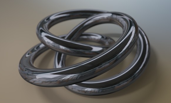
Even though the images above suggests that path tracing is a superior technique, it is also possible to create good looking images in Fragmentarium with the existing ray tracers. For instance, take a look at this image:
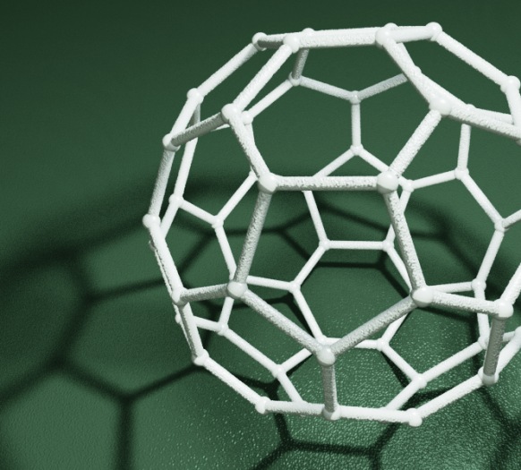

(taken from the Knots and Polyhedra series)

It was ray traced using the 'Soft-Raytracer.frag', and I was not able to improve the render using the Path tracer. Having said that, the Soft-Raytracer is also a multi-sample ray tracer which has to use lots of samples to produce the nice noise-free soft shadows.

References

The Fragmentarium path tracers are still Work-In-Progress, but they can be downloaded here:

Sky-Pathtracer.frag (which needs the Preetham model: Sunsky.frag).

and the image based lighting one:

IBL-Pathtracer.frag

The path tracers can be used by replacing an existing ray tracer '#include' in any Fragmentarium .frag file.

External resources

GI Total Compendium - very valuable collection of all formulas needed for ray tracing.

Vilém Otte's Bachelor Thesis on GPU Path Tracing is a good introduction.

Disney's BRDF explorer - Interactive display of different BRDF models - many examples included. The BRDF definitions are short GLSL snippets making them easy to use in Fragmentarium!

Inigo Quilez's path tracer was the first example I saw of using GPU path tracing of fractals.

Evan Wallace - the first WebGL Path tracer I am aware of.

Brigade is probably the most interesting real time path tracer: Vimeo video and paper.

I would have liked to talk a bit about unbiased and consistent rendering, but I don't understand these issues properly yet. It should be said, however, that since the examples I have given terminate after a fixed number of ray bounces, they will not converge to a true solution of the rendering equation (and, are thus both biased and inconsistent). For consistency, a better termination criterion, such as russian roulette termination, is needed.

Fragmentarium Version 1.0 (“Cologne”) Released

It has been quite a while since the last update to Fragmentarium, but I finally managed to find some time for creating a new release, which indeed is the first release stable enough to qualify as a version “1.0”.

Major changes

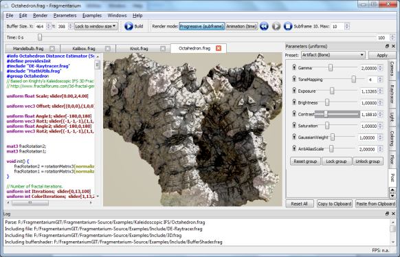
The Fragmentarium UI has been somewhat redesigned in order to simplify it.

Now there are only two modes:

  • Progressive, for creating accumulated images (using multiple samples per pixels). An uniform named ‘subframe’ keeps track of the current frame (and replaces the old ‘backbufferCounter’ uniform).
  • Animation, where a single ‘time’ uniform can be used to control dynamics.

The buffer size no longer needs to be locked to the window size, although it is possible to do so. This means, that it is now possible to work with buffers with different aspect ratio and size than the OpenGL window – something several people had requested.

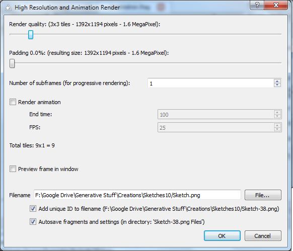
The old ‘Animation Controller’ window is gone. Instead, the time variable may be controlled by a new slider in the main UI. In order the render animation frames, the new ‘High Resolution and Animation Render’ window must be used:

As can be seen, it is now possible to render animations at arbitrary resolution and using multiple subframes. There is also a progress dialog making it possible to actually stop the renders.

The code has also been cleaned up. The prefered build environment is now Qt Creator 2.7 together with Qt 4.8.5 (a project file has been added), though the old VS2008 project has been updated and is working as well (and the Debug configuration now works).

Other changes

  • A “brute-force” raytracer has been added, to render fractals where a distance estimator can not be found.
  • Tile rendering now has added padding option, which can be useful when using screen space methods.
  • New sigmoid tone mapper.
  • IBL raytracer can now rotate maps.

Bug fixes

  • No more mip-maps for non-HDR textures.
  • Fixed some texture caching bugs.
  • And several other minor fixes.

Where to get it

The latest build can be downloaded here (Windows only):
Fragmentarium-Windows-v1.0.0.zip

Mac and Linux users have to download and build from the source tree:
Fragmentarium at GitHub

Image Based Lighting

It can be difficult to achieve realistic lighting by manually placing light sources in a 3D scene. One way to quickly achieve complex and natural lighting is by using real-world light data to lighten the scene.

In order to do that, you need light data from all directions, that is, a full panoramic view. Since you most likely will be looking directly at a light source at some points on your full panorama, you’ll also need to store data that can handle a large dynamic range – 8 bits are not enough.

A common format for these maps is the equirectangular (aka longitude/latitude) format. These are simple 2D bitmaps, typically in 2:1 format, where the x axis covers 360 degrees of azimuthal (longitude) angles, and the y axis covers 180 degrees of elevation (latitude). They are often stored in RGBE (.HDR) files. A good source of free panoramic HDR’s for Image Based Lighting is the sIBL archive.

Backgrounds and reflections

It is very easy to do reflection mapping using equirectangular maps. Simply look up the reflected ray in the equirectangular map. The conversion from 3D direction to map indices is straight-forward:

vec3 equirectangularMap(vec3 dir, sampler2D sampler) {
	// Convert (normalized) dir to spherical coordinates.	
	vec2 longlat = vec2(atan(dir.y,dir.x),acos(dir.z));
	// Normalize, and lookup in equirectangular map.
 	return texture2D(sampler,longlat/vec2(2.0*PI,PI)).xyz;
}

This can also be used to embed the scene in a panoramic view, by looking up the camera ray direction for points that do not hit anything. Here is an example image where reflections and background is sampled from an environment map:

No light model was used in the above image – just pure reflection mapping.

Diffuse light

So what about the diffuse light? Normally, this is modelled by a Lambertian term: the diffuse intensity is proportional to the cosine of the angle between the surface normal and light source direction. In principle, we need to calculate the angle to all points on the hemisphere pointing in the direction of the surface normal, and sum all these contributions. This means, that for each each pixel we raytrace, we need to sample half (one hemisphere) of the pixels in the equirectangular map. Much to slow for even a modern GPU.

But here is the interesting part: the diffuse light contribution is only a function of the surface normal direction. This means we can precalculate the diffuse light in a given normal direction, and store this in a new equirectangular map. Mathematically, this filtering is called a cosine convolution, and some HDR panorama providers are nice enough to provide prefiltered maps for diffuse light (for instance all those in the sIBL archive).

Here is an example of some spheres rendered with specular and diffuse light maps. The materials are faded from pure diffuse (left) to pure specular (right).

As we saw earlier, pure reflection is easy to achieve. But it is also possible to use the Phong reflection model (or other models) with image based lighting. In the Phong model, the specular light intensity depends on the angle between the light source and reflected camera ray. The intensity is proportional to the cosine of this angle raised to a power, which controls the smoothness. Again it is possible to precalculate a convoluted map using the cosine raised to the appropriate power.

Shadows and ground planes

In order to do proper shadows, we would have to check whether the path to every single point on the light map was occluded. Again, this is not feasible. One way to work around this, is to place a single directional light source and then check whether we have a clear to this particular light source. This works nicely, if the light map has a single dominant light source, such as a sun.

But a problem arise since we do not have any background objects to cast shadows on – the objects in the environment map are placed an infinite distance away, and we don’t know their geometry. Consider this image:

There is no sense of the positioning of the objects in this scene – they seem to float at undefinable locations.

To improve this, we can introduce a ground plane, an invisible object, whose only purpose is to catch shadows.

In Fragmentariums IBL-raytracer, you can enable this under the floor tab. It is also possible to turn on some visual debug, to align the floor with the environment map:

Now, once we have set up the ground plane, we can add some ambient occlusion:

… and some shadows:

In order to sample the shadows, we need to sample the area of the light source uniformly. In the case of a sun-like object, this means sampling a hemisphere in a specified direction and for a given latitude span. A formula for this is given in the Global Illumination Compendium (formula 34). To use this, you need to transform the coordinate system to a new one aligned with the light source direction. I do this:

vec3 getSample(vec3 dir, float extent) {
	// Create orthogonal vector (fails for z,y = 0)
	vec3 o1 = normalize(vec3(0., -dir.z, dir.y));
	vec3 o2 = normalize(cross(dir, o1));
	
	// Convert to spherical coords aligned to dir
	vec2 r = getUniformRandomVec2();
	r.x=r.x*2.*PI;
	r.y=1.0-r.y*extent;

	float oneminus = sqrt(1.0-r.y*r.y);
	return cos(r.x)*oneminus*o1+sin(r.x)*oneminus*o2+r.y*dir;
}

Here ‘extent’ is the size of the light source we sample. It is given as ‘1-cos(angle)’, so 0 means a point-like light source (sharp shadows) and 1 means a full hemisphere light source (no shadows).

Notice the construction of the aligned coordinate systems fails if ‘dir’ has zero y and z components – if needed, this should be handled as a special case.

Problems with Simple Image Based Lighting

Since no secondary rays are traced for the specular reflections, some geometry ends up with very unrealistic shading:

The problems here is that the reflections on the inside on the box sees through the sides. So this simple lighting approach works best for convex objects. Here is another example:

(btw, this is Kali’s dragonKIFS system)

Here again the lighting seems unrealistic – something about the specular light is just wrong.

Finally, the combination of the rapidly varying surface normals on a fractal surface and rapidly varying light sources on the environment map introduces new problems. Take a look at this image:

Here there are several small, but strong (HDR) spotlights placed above the Mandelbulb. This image will be very slow to converge and will contain noisy specular highlights: occasionally, one of the subpixel samples will hit a strong light source, which will dominate the sum for the pixel. This will break the sub-pixel anti-aliasing efforts. It is possible to set a maximum (clip) on the specular contributions – or to do HDR tonemapping before averaging – but both solutions goes against the very idea of introducing HDR.

While the specular noise from strong point-like light sources will be difficult to combat, it is easier to do something about the geometry violating reflections.

As of now, I think the best solution is to trace at least secondary rays, and then apply the approximated IBL lighting on the secondary hit points. On problem is that diffuse light does not fall off as quickly as specular light, so you need to sample a lot of points on the hemisphere to get convergence. There are ways around this – for instance, Pixar use bent normals in their Renderman solution, before looking up in the diffuse environment map.

I’ll give a more detailed discussion of the sampling process and the convolution map creation in the next blog post, where I’ll talk about how to speed up diffuse and specular sampling using importance sampling and stratification.

Finally, all the image maps used for lighting on the images accompanying this blog post were from the sIBL archive. And all 3D geometry and composition was of course done in Fragmentarium.

Stereographic Quaternion Julias

Inverse stereographic projections allows you to project a plane onto a sphere. These projections generalize to higher dimensions: for instance, you can inverse project every point in 3D onto the four dimensional 3-sphere. Daniel Piker suggested to use the same transformation to depict the Quaternion Julia systems, instead of using the standard 3D slicing (at least that was what I though – see the update below).

They are still clearly originating from the Quaternions, but the transformation adds a bit of spice. Here are some images:

I’ve previously used stereographic projection to depict Mobius fractals and they were also used to depict the 4D polychora.

For high resolution versions, see my Flickr account.

Update: turns out that what Daniel Piker was suggesting, was to do the stereographic transformation, and then split the 4D coordinates into a starting point and a Julia seed for the ordinary complex (not quaternion) system. I tried this as well, and it creates some very interesting images too:

Rendering 3D fractals without a distance estimator

I have written a lot about distance estimated 3D fractals, and while Distance Estimation is a fast and elegant technique, it is not always possible to derive a distance estimate for a particular system.

So, how do you render a fractal, if the only knowledge you have is whether a given point belongs to the set or not? Or, in other words, how much information can you extract if the only information you have is a black-box function of the form:

bool inside(vec3 point);

I decided to try out some simple brute-force methods to see how they would compare to the DE methods. Contrary to my expectations, it turned out that you can actually get reasonable results without a DE.

First a couple of disclaimers: brute-force methods can not compete with distance estimators in terms of speed. They will typically be a magnitude slower. And if you do have more information available, you should always use it: for instance, even if you can’t find a distance estimator for a given escape time fractal, the escape length contains information that can be used to speed up the rendering or create a surface normal.

The method I used is not novel nor profound: I simply sample random points along the camera ray for each pixel. Whenever a hit is found on the camera ray, the sampling will proceed on only the interval between the camera and the hit point (since we are only interested in finding the closest pixels), e.g. something like this:

for (int i=0; i

(The Near and Far distances are used to restrict the sample space, and speed up rendering)

There are different ways to choose the samples. The simplest is to just sample uniformly (as in the example above), but I found that a stratified approach, where the camera ray segment is divided into equal pieces and a sample is choosen from each part works better. I think the sampling scheme could be improved: in particular once you found a hit, you should probably bias the sampling towards the hit to make convergence faster. Since I use a progressive (double buffered) approach in Fragmentarium, it is also possible to read the pixel depths of adjacent pixels, which probably also could be used.

Now, after sampling the camera rays you end up with a depth map, like this:

(Be sure to render to a texture with 32-bit floats - a 8-bit buffer will cause quantization).

For distance estimated rendering, you can use the gradient of the distance estimator to obtain the surface normal. Unfurtunately this is not an option here. We can, however, calculate a screen space surface normal, based on the depths of adjacent pixels, and transform this normal back into world space:

// Hit position in world space.
vec3 worldPos = Eye + (Near+tex.w*(Far-Near)) * rayDir;

vec3 n = normalize(cross(dFdx(worldPos), dFdy(worldPos)));	

(Update: I found out that GLSL supports finite difference derivatives through the dFdx statement, which made the code above much simpler).

Now we can use a standard lighting scheme, like Phong shading. This really brings a lot of detail to the image:

In order to improve the depth perception, it is possible to apply a screen space ambient occlusion scheme. Recently, there was a very nice tutorial on SSAO on devmaster, but I was to lazy to try it out. Instead I opted for the simplest method I could think of: simply sample some pixels in a neighborhood, and count how many of them that are closer to the camera than the center pixel.

float occ = 0.;
float samples = 0.;
for (float x = -5.; x<=5.; x++) {
  for (float y = -5.; y<=5.; y++) {
    if (x*x+y*y>25.) continue;
    vec3 jitteredPos = pos+vec2(dx*(x+rand(vec2(x,y)+pos)),dy*(y+rand(vec2(x,y)+pos);
    float depth = texture2D(frontbuffer,jitteredPos).w;
    if (depth>=centerDepth) occ+=1.;
    samples++;
  }
}
occ /= samples;

This is how this naive ambient occlusion scheme works:

(Notice that for pixels with no hits, I've choosen to lighten, rather than darken them. This creates an outer glow effect.)

Now combined with the Phong shading we get:

I think it is quite striking how much detail you can infer simply from a depth map! In this case I didn't color the fractal, but nothing prevents you from assigning a calculated color. The depth buffer information only uses the alpha channel.

Here is another example (Aexion's MandelDodecahedron):

While brute-force rendering is much slower than distance estimation, it is possible to render these systems at interactive frame rates in Fragmentarium, especially since responsiveness can be improved by using progressive rendering: do a number of samples, then storing the best found solution (closest pixel) in a depth buffer (I use the alpha channel), render the frame and repeat.

There are a couple of downsides to brute force rendering:

  • It is slower than distance estimation
  • You have to rely on screen space methods for ambient occlusion, surface normals, and depth-of-field
  • Anti-aliasing is more tricky since you cannot accumulate and average. You may render at higher resolution and downsample, or use tiled rendering, but beware that screen space ambient occlusion introduce artifacts which may be visible on tile edges.

On the other hand, there are also advantages:

  • Much simpler to construct
  • Interior renderings are trivial - just reverse the 'inside' function
  • Progressive quality rendering: just keep adding samples, and the image will converge.

To use the Fragmentarium script, just implement an 'inside' function:

#define providesInside
#include "Brute-Raytracer.frag"

bool inside(vec3 pos) {
    // fractal definition here 
}

It is also possible to use the raytracer on existing DE's - here a point is assumed to be inside a fractal if the DE returns a negative number, and outside if the DE returns a positive one.

#include "Brute-Raytracer.frag"

float DE(vec3 pos) {
    // fractal definition here
    // notice, that only the sign of the return value is checked
}

The script can be downloaded as part of Fragmentarium source distribution (it is not yet in the binary distributions). The following files are needed:

Tutorials/3D fractals without a DE.frag
Include/Brute-Raytracer.frag
Include/DepthBufferShader.frag
Include/Brute3D.frag

Fragmentarium Version 0.9.12 (“Prague”) Released

I’ve released a new build of Fragmentarium, version 0.9.12 (“Prague”). It can be downloaded at Github. (Binaries for Windows, source for Windows/Linux/Mac)

The (now standard) caveat apply: Fragmentarium is very much work in progress, and is best suited for people who like to experiment with code.

Version 0.9.12 continues to move Fragmentarium in the direction of progressive HDR rendering. The default raytracers now use accumulated rendering for anti-alias, shadowing, and DOF. To start the progressive rendering, Fragmentarium must be set to ‘Continuous’ mode. It is possible to set a maximum number of rendered frames. All 2D and 3D system now also come with tone mapping, gamma correction, and color control (see the ‘Post’ tab).


IBL Raytracing, using an HDR panorama from Blotchi at HDRLabs.

There is a new raytracer, ‘IBL-raytracer.frag’ which can be used for DE’s instead of the default raytracer. It uses Image Based Lighting from HDR panorama maps. For an example of the new IBL raytracer, see the tutorial: “25 – Image Based Lighting.frag”.

If you need to do stuff like animation, it is still possible to use the old raytracers. They can be included as: “#include “DE-Raytracer-v0.9.1.frag” or “#include “DE-Raytracer-v0.9.10.frag”

Other than that there is now better support for buffer-swap systems (e.g. reaction-diffusion and game-of-life) and better control of texture look-ups.

There are also some interesting new fragments, including the absolutely amazing LivingKIFS.frag script from Kali.

New features

  • Added maximum subframe counter (for progressive rendering).
  • Added support for HDR textures (.hdr RGBE format).
  • Tonemapping, color control, and Gamma correction in buffershader.
  • Added support for widget for changing bound textures.
  • More host defines:
    #define SubframeMax 0
    #define DontClearOnChange   <- when sliders/camera changes, the backbuffer is not cleared.
    #define IterationsBetweenRedraws 20  <- makes it possible to do several steps without updating screen.
    
  • Added texture parameters preprocessor defines:
    #TexParameter texture GL_TEXTURE_MIN_FILTER GL_LINEAR
    #TexParameter texture GL_TEXTURE_MAG_FILTER GL_NEAREST
    #TexParameter texture GL_TEXTURE_WRAP_S GL_CLAMP
    #TexParameter texture GL_TEXTURE_WRAP_T GL_REPEAT
    
  • Change of syntax: when using "#define providesColor", now implement a 'vec3 baseColor(vec3)' function.
  • DE-Raytracer.frag now uses a 'Blinn-Phong with Schickl term and physical normalization'. (Which is something I found in Naty Hoffman's Course Notes).
  • DE-Raytracer.frag and Soft-Raytracer now uses new '3D.frag' base class.
  • Added a texture manager (should reuse and discard textures in memory automatically)
  • Added option to set OpenGL refresh rate in preferences.
  • Progressive2D.frag now supports custom filtering (using '#define providesFiltering')
  • Added support for choosing '#include' through editor context menu.
  • Using arrow keys now work when sliders have focus.
  • Now does a 'reset all' when loading new system (otherwise too confusing).

New fragments

  • Added 'Kali's Creations': KaliBox, LivingKIFS, TreeBroccoli, Xray_KIFS. [Kali]
  • Added Doyle-Spirals.frag [Knighty]
  • Added: Droste.frag (Escher Droste effect)
  • Added: Reaction-Diffusion.frag (Gray-Scott example)
  • Added 'Convolution.frag' example (For precalculating specular and diffuse lighting from HDR panoramas)
  • Added examples of working with double precision floats and emulated double precision floats: "Include/EmulatedDouble.frag", "Theory/Mandelbrot - Emulated Doubles.frag"
  • Added 'IBL-Raytracer.frag' (Image Based Lighting raytracer)
  • Added tutorials: 'progressive2D.frag' and 'pure3D.frag'
  • Added experimental: 'testScene.frag' and 'triplanarTexturing.frag'
  • Added 'Thorn.frag'

Bug fixes

  • Reflection is now working again in 'DE-Raytracer.frag'
  • Fixed filename case sensitivity error when doing reverse lookup of line numbers.

Mac users

Some Mac users has reported problems with the latest versions of Fragmentarium. Again, I don't own a Mac, so I cannot solve these issues without help.

For examples of images generated with the new version, take a look at the Flickr Fragmentarium stream.

Finally, please read the FAQ, before asking questions.

Gamma Correction

Gamma correction is certainly not the most sexy topic in computer graphics. But it needs to be taken into account whenever you perform almost any kind of graphical manipulation.

The most widely used way to transfer image and color information is by encoding them as 8-bit RGB colors. Unfortunately, the human eye does not perceive brightness linearly as a function of the physical intensity. Since we are dealing with only 256 levels for each color channel, we apply a non-linear encoding – a gamma encoding – to make the most of our limited bits – otherwise we would experience banding in the range where the eye is most sensitive.

Typically, a simple power law is used: \(Encoded = Linear^{0.45}\)

The display hardware then performs the inverse transformation for the final output: \(Linear = Encoded^{1/0.45} = Encoded^{2.2}\). This last exponent (2.2) is referred to as the gamma value.

On a modern computer, this means that all 8-bit media (your typical images, such as JPG’s and PNG’s) are gamma encoded, and not stored with linear intensities. The 8-bit framebuffers that are sent to the GPU, are also expected to be gamma encoded to make the most of the limited range. So far, all is well: you can read an image from a JPG and send it directly to the framebuffer – it will then display correct.

But problems arise when you start manipulating the graphics data. For instance, imagine you are downsizing an image with a checkerboard pattern of pure white and pure black pixels, until is small enough to be constant colored. You might guess, that the proper average value should be 0.5 (this discussion assumes that color values are not in the integer range [0,255], but normalized to [0,1]). But if you are working in gamma corrected space, the correct value is (0.5^(1/2.2)) =~ 0.73. This is the value you should send to the framebuffer in order to get an average physical intensity of pure black and white on your monitor. Notice that all browsers, and many photo manipulation programs fail to perform correct gamma-aware resizing.

The same applies to 3D graphics. All these lighting and shades techniques (e.g. Blinn-Phong shading) are designed to work in linear intensity space.

So the correct procedure when working with graphics is to convert all gamma encoded media to linear intensities, perform any calculation/blending/averaging, and convert back to gamma encoding. Notice, that this requires that you use something with more resolution than 8-bit integers (typically 32-bit floats) when working in linear space. Otherwise, too much resolution would be lost, and the whole point of gamma encoding would be lost. Also notice that media and images in high dynamic formats, such as HDR (.rgbe) and RAW typically are in linear space and should not be converted.

The following image sums up when and how to use gamma encoding and do conversions:

Here is an example of an image with and without a gamma-aware rendering pipeline:

The image on the left has been rendered completely ignoring gamma. The image on the right has proper gamma handling. Notice, that gamma-aware rendering does not necessarily look better – If you turn on gamma correct rendering, you images will be lighter, and might loose contrast, so you might have to adjust light sources and exposure.

Gamma Correction in Fragmentarium

In Fragmentarium the base classes “Progressive2D.frag” and “DE-raytracer.frag” are both gamma-aware. When you implement a color function, e.g. for the 2D case:

vec3 color(vec2 pos) { ... }

and for the 3D case:

#define providesColor
vec3 baseColor(vec2 pos) { ... }

the returned color is expected to be gamma corrected. If you want to supply linear colors, insert a

#define linearGamma

at the top of the script.

And all the rest…

Many gamma discussions on the internet revolve around how old CRT monitors expected a non-linear input. And it is indeed true that older CRT monitors had a relation between the light intensity and the applied voltage which was roughly like: \(intensity = voltage^{2.5}\). But modern displays, such as the TFT panels, do not have similar simple power law relations between the voltage and the intensity. Still, when you send 8-bit data to the framebuffer, you must gamma encode it, with a gamma of around 2.2. This will not change for as long as 8-bit data is used as data transfer format.

A few other points:

  • The encoding expected and used for 8-bit format is not always a simple gamma power-law relation. More often the sRGB encoding is used. It is, however, very similar to a power-2.2 gamma encoding, and for most applications, the difference is not important.
  • For a good discussion of what exactly is meant by intensity and brightness, see the Gamma FAQ.
  • OpenGL and Direct3D may perform sRGB encoding/decoding directly in hardware. This is the preferred way, since for instance texture interpolation is performed correctly.
  • Sometimes linear intensities are stored in 8-bit data, despite the loss of perceived dynamic levels. This might be the case in game pipelines (to reduce data size).

Further reading:
Naty Hoffman’s Adventures with Gamma-Correct Rendering
GPU Gems 3: The Importance of Being Linear

Reaction-Diffusion Systems

Reaction-diffusion systems model the spatial dynamics of chemicals. An interesting early application was Alan Turing’s theory of Morphogenesis (Turing’s 1951 paper). Here, he suggested, that the pattern formation in animal skin could be explained by a two component reaction-diffusion system.

Reaction-diffusion systems are interesting, because they display a wide range of self-organizing patterns, and they have been used by several digital artists, both for 2D pattern generation and 3D structure generation.

The reaction-diffusion model is a great example of how complex large-scale structure may emerge from simple, local rules.

Modelling Reaction-Diffusion on a GPU

As the name suggests, these systems have two driving components: diffusion, which tends to spread out or smoothen concentrations, and reactions, which describe how chemical species may transform into each other.

For each chemical species, it is possible to describe the evolution using a differential equation on the form:

\(\frac {dA}{dt} = K \nabla^2 A + P(A,B)\)
 
Where A and B are fields describing the concentration of a chemical species at each point in space. The \(K\) coefficient determines how quickly the concentration spreads out, and \(P(A,B)\) is a polynomial in the different species concentrations in the system. There will be a similar equation for the B field.

To model these, we can represent the concentrations on a discrete grid, which fits nicely on a 2D texture on a GPU. The time derivative can solved in discrete time steps using forward Euler integration (or something more powerful). On a GPU, we need two buffers to do this: we render the next time step into the front buffer using values from the back buffer, and then swap the buffers.

Buffer swapping is a standard technique, and in Fragmentarium the only thing you need to do, is to declare a ‘uniform sampler2D backbuffer;’ and Fragmentarium will take care of creation and swapping of buffers. We also use the Fragmentarium host define ‘#buffer RGBA32F’ to ask for four-component 32-bit float buffers, instead of the normal 8-bit integer buffers.

The Laplacian may be calculated using a finite differencing scheme, for instance using a five-point stencil:

vec3 P = vec3(pixelSize, 0.0); 

// Five point stencil Laplacian
vec4  laplacian5() {
	return 
	+  texture2D( backbuffer, position - P.zy)
	+  texture2D( backbuffer, position - P.xz) 
	-  4.0 * texture2D( backbuffer,  position )
	+ texture2D( backbuffer,  position + P.xz )
	+ texture2D( backbuffer,  position +  P.zy );
}

(see the Fragmentarium source for a nine-point stencil).

A simple two-component Gray-Scott system may then be modelled simply as:

// time step for Gray-Scott system:
vec4 v = texture2D(backbuffer, position);
vec2 lv = laplacian5().xy; // laplacian
float xyy = v.x*v.y*v.y;   // utility term
vec2 dV = vec2( Diffusion.x * lv.x - xyy + f*(1.-v.x), Diffusion.y * lv.y + xyy - (f+k)*v.y);
v.xy += timeStep*dV;

(Robert Munafo has a great page with more information on Gray-Scott systems).

Here is an example of a typical system created using the above system, though many other patterns are possible:

It is also possible to enforce some structure by changing the concentrations in certain regions:

You can even use a picture to modify the concentrations:

A template implementation can be found as part of the Fragmentarium source at GitHub: Reaction-Diffusion.frag. Notice, that this fragment requires a recent source build from the GitHub repository to run.

Reaction-Diffusion systems used by artists

Several artist have used Reaction Diffusion systems in different ways, but the most impressive examples of 2D images I have seen, are the works of Jonathan McCabe. For instance his Bone Music series: or his Turing Flow series:

McCabe’s images are created using a more complex multi-scale model. Softology’s blog entry and W:Blut’s post dissect McCabe’s approach (there is even a reference implementation in Processing). Notice, that Nervous System sells some of McCabe’s works as jigsaw puzzles.

Reaction-Diffusion systems in WebGL

Felix Woitzel (@Flexi23) has created some beautiful WebGL-based reaction-diffusion demos, such as this Fluid simulation with Turing patterns:


He also has created several other RD based variants over at WebGL Playground.

Fabricated 3D Objects

Jessica Rosenkrantz and Jesse Louis-Rosenberg at Nervous System create and sell objects designed and inspired by generative processes. Several of their objects, including these cups, plates, and lamps are based on reaction-diffusion systems, and can be bought from their webshop.

Be sure to read their blog entries about reaction-diffusion. And don’t forget to take a look at their Cell Cycle WebGL design app, while visiting.

Reaction-Diffusion Software

An easy way to explore reaction-diffusion systems with doing any coding is by using Ready, which uses OpenCL to explore RD systems. It has several interesting features, including the ability to run systems on 3D meshes and directly interact and ‘paint’ on the surfaces.

It also lets you run Game-of-Life on exotic geometries, such as a torus or even something as exotic as a Penrose tiling.

Double Precision in OpenGL and WebGL

This post talks about double precision numbers in OpenGL and WebGL, and how to emulate them if there is no native hardware support.

In GLSL 4.00.9 (which is OpenGL 4.0) and higher, there is a native double precision floating point type. And if your graphics card is able to run OpenGL 4.0, it most likely has native hardware support for doubles (except for a few ATI/AMD cards). There are some caveats, though:

  1. Not all functions are supported with double precision arguments. For instance, there are no trigonometric and exponential functions. (The available functions may be found here).
  2. You can not pass double precision ‘varying’ parameters from the vertex shader to the fragment shader, and have the GPU automatically interpolate them. Double precision varying variables must be flat.
  3. Double precision performance may be artificially limited by the hardware manufacturers. This is the case for Nvidia’s Fermi architecture, where the scientific computing brand, the Tesla series, can execute double precision arithmetics at half the speed of single precision, while the consumer brand, the GeForce series, only can execute double precision arithmetics at 1/8 the speed of single precision. For Nvidia’s brand new Kepler architecture used in the GeForce 600 series, things change again: here the difference between single and double precision will be a whopping factor 24! Notice, that this will also be the case for some cards in the Kepler Tesla branch, such as the Tesla K10.
  4. In Fragmentarium (and in general, in Qt’s OpenGL wrapper classes) it is not possible to set double precision uniforms. This should be easy to circumvent by using the OpenGL API directly, though.


(Non-related Fragmentarium image)

In order to use double precision, you must either specify a GLSL version 4.00 (or higher) or use the extension:

#extension GL_ARB_gpu_shader_fp64 : enable

Older cards, like the GeForce 310M in my laptop, does not support double precision in hardware. Here it is possible to use emulated double precision instead.

I used the functions by Henry Thasler described here in his posts, to emulate a double precision number stored in two single precision floats. The worst part about doing emulated doubles in GLSL, is that GLSL does not support operator overloading. This means the syntax gets ugly for simple arithmetics, e.g. ‘z = add(mul(z1,z2),z3)’ instead of ‘z = z1*z2+z3’.

On Nvidia cards, it is necessary to turn off optimization to use Thasler’s code – this can be done using the following pragmas:

#pragma optionNV(fastmath off)
#pragma optionNV(fastprecision off)


(Non-related Fragmentarium image)

Performance

To test performance, I used a Mandelbrot test scene, rendered at 1000×500 with 1000 iterations in Fragmentarium. The numbers show the performance in frames per second. The zoom factor was determined visually, by noticing when pixelation occurred.

Geforce 570GTX Tesla 2075 Max Zoom
(~300USD) (~2200USD)
Single 140 100 10^5
Double 41 70 10^14
Emulated Double 16 11 10^13

Some observations:

  • Emulated double precision is slightly less accurate then true hardware doubles, but not much in this particular scenario.
  • Emulated doubles are roughly 1/9th the speed of single precision. Amazingly, this suggest that on the Kepler architecture it might make more sense to use emulated double precision than the built-in hardware support!
  • Hardware doubles on the 570GTX performs better than expected (they should perform at roughly 1/8 the speed). This is probably because double precision arithmetics isn’t the only bottleneck in the shader.

Notice that the Tesla card was running on Windows in WDDM mode, not TCC mode (since you cannot use GLSL shaders in TCC mode). Not that I think performance would change.

WebGL and double precision

WebGL does not support double precision in its current incarnation. This might change in the future, but currently the only choice is to emulate them. This, however, is problematic since WebGL seems to strip away pragmas! Henry Thasler’s emulation code doesn’t work under the ANGLE layer either. In fact, the only configuration I could get to work, was on a Intel HD 3000 GPU with ANGLE disabled. I did create a sample application to test this which can be tried out here:
Click to run WebGL app. Left side is single-precision, right side is emulated double precision. Here shown on Firefox without ANGLE on a Intel HD 3000 card.

It is not clear why the WebGL version does not work on Nvidia cards. Floating points may run at lower resolution in WebGL, but I’m using the ‘precision highp’ qualifiers. I also tried querying the resolution using glContext.getShaderPrecisionFormat(…), but had no luck – it is only available on Firefox, and on my GPU’s it just returns precision=0.

The most likely explanation is that Nvidia drivers perform some optimizations which spoils the emulation code. This is also the case for desktop OpenGL, but here the pragma’s solve the problem.

The emulation code uses constructs like:

z = a - (a - b);

which I suspect the well-meaning compiler might translate to ‘z=b’, since the rounding errors normally would be insignificant. Judging from some comments on Thasler’s original posts, it might be possible to prevent this using constructs such as: ‘z = a – float(a-b)’, but I have not pursued this.

Fragmentarium and Double Precision

Except that there are no double-precision sliders (uniforms), it is straight-forward to use double precision code in Fragmentarium. The only thing to remember is that you cannot pass doubles from the vertex shader to the fragment shader, which is the standard way of passing camera information to the shader in Fragmentarium.

I’ve also included a small port of Thaslers GLSL code in the distribution (see “Include/EmulatedDouble.frag”). It is quite easy to use (for an example, try the included “Theory/Mandelbrot – Emulated Doubles.frag”).

The Map and the Territory

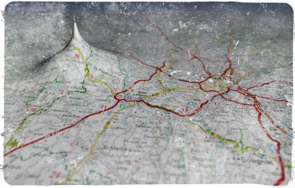
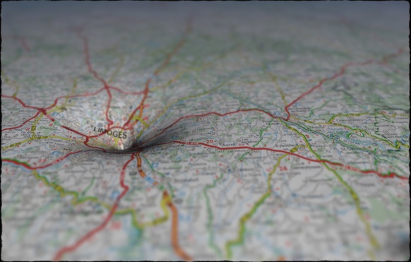
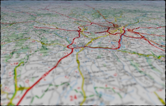
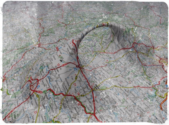
In Michel Houellebecq’s novel The Map and the Territory, the (fictional) principal character gains some fame by creating a series of photographs of Michelin road maps. Some of the images are described in detail: in particular one taken of a map near the village of Châtelus-le-Marcheix.

I decided to recreate this (using Fragmentarium to simulate the camera optics). And of course I couldn’t resist to add a few singularities to the projection model.

As for the maps, I used the online version of Michelin’s road maps taken from the same region – hopefully this qualifies as fair use.

Click the images to see a larger version – these images work better when viewed large.