Previous parts: part I, part II, part III, part IV, part V, and part VI.
This was supposed to be the last blog post on distance estimated 3D fractals, but then I stumbled upon the dual number formulation, and decided it would blend in nicely with the previous post. So this blog post will be about dual numbers, and the next (and probably final) post will be about hybrid systems, heightmap rendering, interior rendering, and links to other resources.
Dual Numbers
Many of the distance estimators covered in the previous posts used a running derivative. This concept can be traced back to the original formula for the distance estimator for the Mandelbrot set, where the derivative is described iteratively in terms of the previous values:
\(f’_n(c) = 2f_{n-1}(c)f’_{n-1}(c)+1\)
In the previous post, we saw how the Mandelbox could be described a running Jacobian matrix, and how this matrix could be replaced by a single running scalar derivative, since the Jacobians for the conformal transformations all have a particular simple form (and thanks to Knighty the argument was extended to non-Julia Mandelboxes).
Now, some month ago I stumbled upon automatic differentation and dual numbers, and after having done some tests, I think this a very nice framework to complete the discussion of distance estimators.

So what are these dual numbers? The name might sound intimidating, but the concept is very simple: we extend the real numbers with another component – much like the complex numbers:
\(x = (x_r, x_d) = x_r + x_d \epsilon\)where \(\epsilon\) is the dual unit, similar to the imaginary unit i for the complex numbers. The square of a dual unit is defined as: \(\epsilon * \epsilon = 0\).
Now for any function which has a Taylor series, we have:
\(f(x+dx) = f(x) + f'(x)dx + (f”(x)/2)dx^2 + …\)
If we let \(dx = \epsilon\), it follows:
\(f(x+\epsilon) = f(x) + f'(x)\epsilon \)
because the higher order terms vanish. This means, that if we evaluate our function with a dual number \(d = x + \epsilon = (x,1)\), we get a dual number back, (f(x), f'(x)), where the dual component contains the derivative of the function.
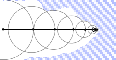
Compare this with the finite difference scheme for obtaining a derivative. Take a quadratic function as an example and evaluate its derivative, using a step size ‘h’:
\(f(x) = x*x\)This gives us the approximate derivative:
\(f'(x) \approx \frac {f(x+h)-f(x)}{h} = \frac { x^2 + 2*x*h + h^2 – x^2 } {h} = 2*x+h\)
The finite difference scheme introduces an error, here equal to h. The error always gets smaller as h gets smaller (as it converges towards to the true derivative), but numerical differentiation introduces inaccuracies.
Compare this with the dual number approach. For dual numbers, we have:
\(x*x = (x_r+x_d\epsilon)*(x_r+x_d\epsilon) = x_r^2 + (2 * x_r * x_d )\epsilon\).
Thus,
\(f(x_r + \epsilon) = x_r^2 + (2 * x_r)*\epsilon\)
Since the dual component is the derivative, we have f'(x) = 2*x, which is the exact answer.
But the real beauty of dual numbers is, that they make it possible to keep track of the derivative during the actual calculation, using forward accumulation. Simply by replacing all numbers in our calculations with dual numbers, we will end up with the answer together with the derivative. Wikipedia has a very nice article, that explains this in more details: Automatic Differentation. The article also list several arithmetric rules for dual numbers.
For the Mandelbox, we have a defining function R(p), which returns the length of p, after having been through a fixed number of iterations of the Mandelbox formula: scale*spherefold(boxfold(z))+p. The DE is then DE = R/DR, where DR is the length of the gradient of R.
R is a scalar-valued vector function. To find the gradient we need to find the derivative along the x,y, and z direction. We can do this using dual vectors and evaluate the three directions, e.g. for the x-direction, evaluate \(R(p_r + \epsilon (1,0,0))\). In practice, it is more convenient to keep track of all three dual vectors during the calculation, since we can reuse part of the calculations. So we have to use a 3×3 matrix to track our derivatives during the calculation.
Here is some example code for the Mandelbox:
// simply scale the dual vectors
void sphereFold(inout vec3 z, inout mat3 dz) {
	float r2 = dot(z,z);
	if (r2 < minRadius2) {
		float temp = (fixedRadius2/minRadius2);
		z*= temp; dz*=temp;
	} else if (r2 < fixedRadius2) {
		float temp =(fixedRadius2/r2);
                dz[0] =temp*(dz[0]-z*2.0*dot(z,dz[0])/r2);
                dz[1] =temp*(dz[1]-z*2.0*dot(z,dz[1])/r2);
                dz[2] =temp*(dz[2]-z*2.0*dot(z,dz[2])/r2);
		z*=temp; dz*=temp;
	}
}

// reverse signs for dual vectors when folding
void boxFold(inout vec3 z, inout mat3 dz) {
	if (abs(z.x)>foldingLimit) { dz[0].x*=-1; dz[1].x*=-1; dz[2].x*=-1; }
        if (abs(z.y)>foldingLimit)  { dz[0].y*=-1; dz[1].y*=-1; dz[2].y*=-1; }
        if (abs(z.z)>foldingLimit)  { dz[0].z*=-1; dz[1].z*=-1; dz[2].z*=-1; }
	z = clamp(z, -foldingLimit, foldingLimit) * 2.0 - z;
}

float DE(vec3 z)
{
        // dz contains our three dual vectors,
        // initialized to x,y,z directions.
	mat3 dz = mat3(1.0,0.0,0.0,0.0,1.0,0.0,0.0,0.0,1.0);

	vec3 c = z;
	mat3 dc = dz;
	for (int n = 0; n < Iterations; n++) {
		boxFold(z,dz);
		sphereFold(z,dz);
		z*=Scale;
		dz=mat3(dz[0]*Scale,dz[1]*Scale,dz[2]*Scale);
		z += c*Offset;
	        dz +=matrixCompMult(mat3(Offset,Offset,Offset),dc);
		if (length(z)>1000.0) break;
	}
	return dot(z,z)/length(z*dz);
}
The 3×3 matrix dz contains our three dual vectors (they are stored as columns in the matrix, dz[0], dz[1], dz[2]).
In order to calculate the dual numbers, we need to know how to calculate the length of z, and how to divide by the length squared (for sphere folds).
Using the definition of the product for dual numbers, we have:
\(|z|^2 = z \cdot z = z_r^2 + (2 z_r \cdot z_d)*\epsilon\)For the length, we can use the power rule, as defined on Wikipedia:
\(|z_r + z_d \epsilon| = \sqrt{z_r^2 + (2 z_r \cdot z_d)*\epsilon}
= |z_r| + \frac{(z_r \cdot z_d)}{|z_r|}*\epsilon\)
Using the rule for division, we can derive:
\(z/|z|^2=(z_r+z_d \epsilon)/( z_r^2 + 2 z_r \cdot z_d \epsilon)\)
\( = z_r/z_r^2 + \epsilon (z_d*z_r^2-2z_r*z_r \cdot z_d)/z_r^4\)
Given these rules, it is relatively simple to update the dual vectors: For the sphereFold, we either multiply by a real number or use the division rule above. For the boxFold, there is both multiplication (sign change), and a translation by a real number, which is ignored for the dual numbers. The (real) scaling factor is also trivially applied to both real and dual vectors. Then there is the addition of the original vector, where we must remember to also add the original dual vector.
Finally, using the length as derived above, we find the length of the full gradient as:
\(DR = \sqrt{ (z_r \cdot z_x)^2 + (z_r \cdot z_y)^2 + (z_r \cdot z_z)^2 } / |z_r|\)
In the code example, the vectors are stored in a matrix, which makes a more compact notation possible: DR = length(z*dz)/length(z), leading to the final DE = R/DR = dot(z,z)/length(z*dz)

There are some advantages to using the dual numbers approach:
- Compared to the four-point Makin/Buddhi finite difference approach the arbitrary epsilon (step distance) is avoided – which should give better numerical accuracy. It is also somewhat slightly faster computationally.
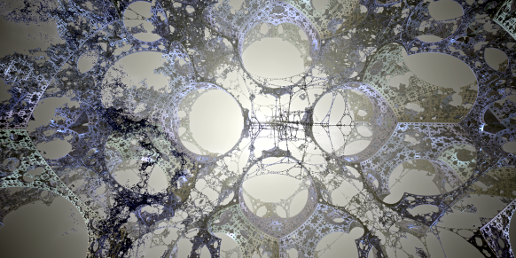
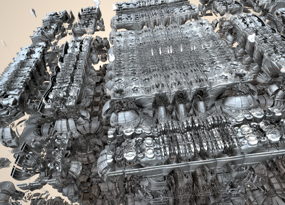
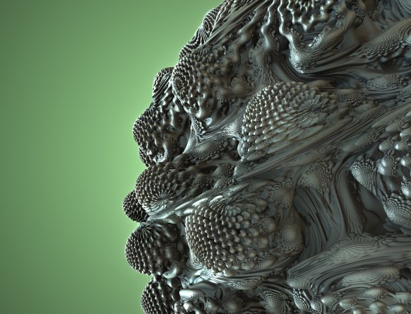
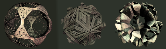
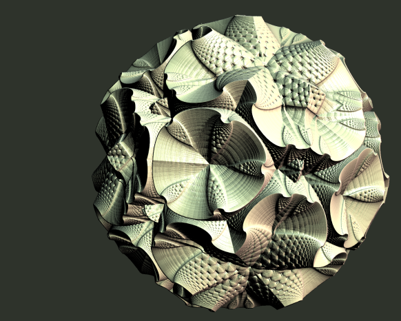
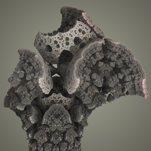
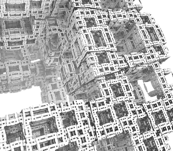
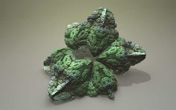
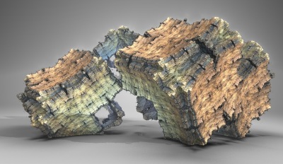
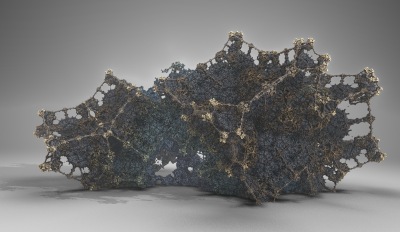
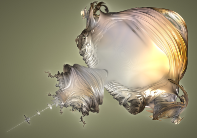
- Very general – e.g. works for non-conformal cases, where running scalar derivatives fail. The images here are from a Mandelbox where a different scaling factor was applied to each direction (making them non-conformal). This is not possible to capture in a running scalar derivative.
On the other hand, the method is slower than using running scalar estimators. And it does require code changes. It should be mentioned that libraries exists for languages supporting operator overloading, such as C++.
Since we find the gradient directly in this method, we can also use it as a surface normal – this is also an advantage compared to the scalar derivates, which normally use a finite difference scheme for the normals. Using the code example the normal is:
// (Unnormalized) normal
vec3 normal = vec3(dot(z,dz[0]),dot(z,dz[1]),dot(z,dz[2]));
It should be noted that in my experiments, I found the finite difference method produced better normals than the above definition. Perhaps because it smothens them? The problem was somehow solved by backstepping a little before calculating the normal, but this again introduces an arbitrary distance step.
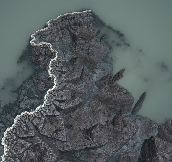
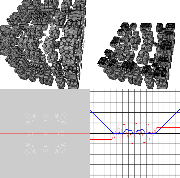
Now, I said the scalar method was faster – and for a fixed number of ray steps it is – but let us take a closer look at the distance estimator function:

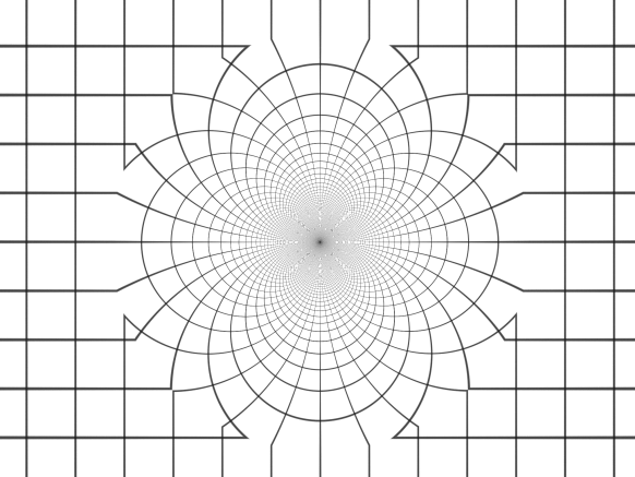
The above image shows a sliced Mandelbox.
The graph in the lower right conter shows a plot of the DE function along a line (two dimensions held fixed): The blue curve is the DE function, and the red line shows the derivative of the DE function. The function is plotted for the dual number derived DE function. We can see that our DE is well-behaved here: for a consistent DE the slope can never be higher than 1, and when we move away from the side of the Mandelbox in a perpendicular direction the derivative of the DE should be plus or minus one.
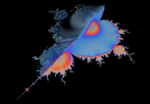
Now compare this to the scalar estimated DE:
Here we see that the DE is less optimal – the slope is ~0.5 for this particular line graph. Actually, the slope would be close to one if we omitted the ‘+1’ term for the scalar estimator, but then it overshoots slightly some places inside the Mandelbox.
We can also see that there are holes in our Mandelbox – this is because for this fixed number of ray steps, we do not get close enough to the fractal surface to hit it. So even though the scalar estimator is faster, we need to crank up the number of ray steps to achieve the same quality.
Final Remarks
The whole idea of introducing dual derivatives of the three unit vectors seems to be very similar to having a running Jacobian matrix estimator – and I believe the methods are essentially idential. After all we try to achieve the same: keeping a running record of how the R(p) function changes, when we vary the input along the axis.
But I think the dual numbers offer a nice theoretical framework for calculating the DE, and I believe they could be more accurate and faster then finite difference four point gradient methods. However, more experiments are needed before this can be asserted.
Scalar estimators will always be the fastest, but they are probably only optimal for conformal systems – for non-conformal system, it seems necessary to introduce terms that make them too conservative, as demonstrated by the Mandelbox example.
The final part contains all the stuff that didn’t fit in the previous posts, including references and links.