I have written a lot about distance estimated ray marching using OpenGL shaders on this blog.
But one of the things I have always left out is how to setup the camera and perspective projection in OpenGL. The traditional way to do this is by using functions such as ‘gluLookAt’ and ‘gluPerspective’. But things become more complicated if you want to combine ray marched shader graphics with the traditional OpenGL polygons. And if you are using modern OpenGL (the ‘core’ context), there is no matrix stack and no ‘gluLookAt’ functions. This post goes through through the math necessary to combine raytraced and polygon graphics in shaders. I have seen several people implement this, but I couldn’t find a thorough description of how to derive the math.
Here is the rendering pipeline we will be using:
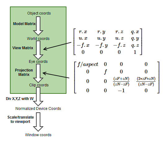
It is important to point out, that in modern OpenGL there is no such thing as a model, view, or projection matrix. The green part on the diagram above is completely programmable, and it is possible to do whatever you like there. Only the part after the green box of the diagram (starting with clip coordinates) is fixed by the graphics card. But the goal here is to precisely match the convention of the fixed-function OpenGL pipeline matrices and the GLU functions gluLookAt and gluPerspective, so we will stick to the conventional model, view, and projection matrix terminology.
The object coords are the raw coordinates, for instance as specified in VBO buffers. This is the vertices of an 3D object in its local coordinate system. The next step is to position and orient the 3D object in the scene. This is accomplished by applying the model matrix, that transform the object coordinates to global world coordinates. The model transformation will be different for the different objects that are placed in the scene.
The camera transformation
The next step is to transform the world coordinates into camera or eye space. Now, neither old nor modern OpenGL has any special support for implementing a camera. Instead the conventional gluPerspective always assumes an origo centered camera facing the negative z-direction, and with an up-vector in the positive y-direction. So, in order to implement a generic, movable camera, we instead find a camera-view matrix, and then apply the inverse transformation to our world coordinates – i.e. instead of moving/rotate the camera, we apply the opposite transformation to the world.
Personally, I prefer using a camera specified using a forward, up, and right vector, and a position. It is easy to understand, and the only problem is that you need to keep the vectors orthogonal at all times. So we will use a camera identical to the one implemented in gluLookAt.
The camera-view matrix is then of the form:
\(
\begin{bmatrix}
r.x & u.x & -f.x & p.x \\
r.y & u.y & -f.y & p.y \\
r.z & u.z & -f.z & p.z \\
0 & 0 & 0 & 1
\end{bmatrix}
\)
where r=right, u=up, f=forward, and p is the position in world coordinates. R, u, and f must be normalized and orthogonal.
Which gives an inverse of the form:
\(
\begin{bmatrix}
r.x & r.y & r.z & q.x \\
u.x & u.y & u.z & q.y \\
-f.x & -f.y & -f.z & q.z \\
0 & 0 & 0 & 1
\end{bmatrix}
\)
By multiplying the matrices together and requiring the result is the identity matrix, the following relations between p and q can be established:
q.x = -dot(r,p), q.y = -dot(u,p), q.z = dot(f,p)
p = -vec3(vec4(q,0)*modelView);
As may be seen, the translation part (q) of this matrix is the position of the camera expressed in the R,u, and f coordinate system.
Now, per default, the OpenGL shaders use a column-major representation of matrices, in which the data is stored sequentially as a series of columns (notice, that this can be changed by specifying ‘layout (row_major) uniform;’ in the shader). So creating the model-view matrix as an array on the CPU side looks like this:
float[] values = new float[] {
    r[0], u[0], -f[0], 0,
    r[1], u[1], -f[1], 0,
    r[2], u[2], -f[2], 0,
    q[0], q[1], q[2], 1};
Don’t confuse this with the original camera-transformation: it is the inverse camera-transformation, represented in column-major format.
The Projection Transformation
The gluPerspective transformation uses the following matrix to transform from eye coordinates to clip coordinates:
\(
\begin{bmatrix}
f/aspect & 0 & 0 & 0 \\
0 & f & 0 & 0 \\
0 & 0 & \frac{(zF+zN)}{(zN-zF)} & \frac{(2*zF*zN)}{(zN-zF)} \\
0 & 0 & -1 & 0
\end{bmatrix}
\)
where ‘f’ is cotangent(fovY/2) and ‘aspect’ is the width to height ratio of the output window.
(If you want to understand the form of this matrix, try this link)
Since we are going to raytrace the view frustum, consider what happens when we transform an direction of the form (x,y,-1,0) from eye space to clip coordinates and further to normalized device coordinates. Since the clip.w in this case will be 1, the x and y part of the NDC will be:
ndc.xy = (x*f/aspect, y*f)
Since normalized device coordinates range from [-1;1], this means that when we ray trace our frustrum, our ray direction (in eye space) must be in the range:
eyeX = [-aspect/f ; aspect/f]
eyeY = [-1/f ; 1/f]
eyeZ = -1
where 1/f = tangent(fovY/2).
We now have the necessary ingredients to set up our raytracing shaders.
The polygon shaders
But let us start with the polygon shaders. In order to draw the polygons, we need to apply the model, view, and projection transformations to the object space vertices:
gl_Position = projection * modelView * vertex;
Notice, that we premultiply the model and view matrix on the CPU side. We don’t need them individually on the GPU side. If you wonder why we don’t combine the projection matrix as well, it is because we want to use the modelView to transform the normals as well:
eyeSpaceNormal = mat3(modelView) * objectSpaceNormal;
Notice, that in general normals transform different from positions. They should be multiplied by the inverse of the transposed 3×3 part of the modelView matrix. But if we only do uniform scaling and rotations, the above will work, since the rotational part of matrix is orthogonal, and the uniform scaling does not matter if we normalize our normals. But if you do non-uniform scaling in the model matrix, the above will not work.
The raytracer shaders
The raytracing must be done in world coordinates. So in the vertex shader for the raytracer, we need figure out the eye position and ray direction (both in world coordinates) for each pixel. Assume that we render a quad, with the vertices ranging from [-1,-1] to [1,1].
The eye position can be easily found from the formula found under ‘the camera transformation’:
eye = -(modelView[3].xyz)*mat3(modelView);
Similar, by transforming the ranges we found above from eye to world space we get that:
dir = vec3(vertex.x*fov_y_scale*aspect,vertex.y*fov_y_scale,-1.0)
	*mat3(modelView);
where fov_y_scale = tangent(fovY/2) is an uniform calculated on the CPU side.
Normally, OpenGL takes care of filling the z-buffer. But for raytracing, we have to do it manually, which can be done by writing to gl_fragDepth. Now, the ray tracing takes place in world coordinates: we are tracing from the eye position and into the camera-forward direction (mixed with camera-up and camera-right). But we need the z-coordinate of the hit position in eye coordinates. The raytracing is of the form:
vec3 hit = p + rayDirection * distance; // hit in world coords
Converting the hit point to eye coordinates gives (the p and q terms cancel):
eyeHitZ = -distance * dot(rayDirection * cameraForward);
which in clip coordinates becomes:
clip.z = [(zF+zN)/(zN-zF)]*eyeHitZ +  (2*zF*zN)/(zN-zF);
clip.w = -eyeHitZ;
Making the perspective divide, we arrive at normalized device coordinates:
ndcDepth = ((zF+zN) + (2*zF*zN)/eyeHitZ)/(zF-zN)
The ncdDepth is in the interval [-1;1]. The last step that remains is to convert into window coordinates. Here the depth value is mapped onto an interval determined by the gl_DepthRange.near and gl_DepthRange.far parameters (usually these are just 0 and 1). So finally we arrive at the following:
gl_FragDepth =((gl_DepthRange.diff * ndcDepth) + gl_DepthRange.near + gl_DepthRange.far) / 2.0;
Putting the pieces together, we arrive at the following for the ray tracing vertex shader:
void main(void)
{
  gl_Position = vertex;
  eye = -(modelView[3].xyz)*mat3(modelView);
  dir = vec3(vertex.x*fov_y_scale*aspect,vertex.y*fov_y_scale,-1.0)
			*mat3(modelView);
  cameraForward = vec3(0,0,-1.0)*mat3(modelView);
}
and this code for the fragment shader:
void main (void)
{
  vec3 rayDirection=normalize(dir);
  trace(eye,rayDirection, distance, color);
  fragColor = color;
  float eyeHitZ = -distance *dot(cameraForward,rayDirection);
  float ndcDepth = ((zFar+zNear) + (2.0*zFar*zNear)/eyeHitZ)
		/(zFar-zNear);
  gl_FragDepth =((gl_DepthRange.diff * ndcDepth)
		+ gl_DepthRange.near + gl_DepthRange.far) / 2.0;
}
The above is of course just snippets. I’m currently experimenting with a Java/JOGL implementation of the above (Github repo), with some more complete code.
Great blog post! I’ve been studying matrices and coordinate space transformations the past couple of weeks with the intention of implementing exactly what you just described! Thank you for the great resource!
Cheers
Keith
Hi, I just wanted to point out a correction on your matrix transform pipeline. You seem to have the model matrix confused with the view matrix(“camera matrix”). However, it is labeled correctly in your first diagram with the green box.
“The next step is to position and orient the 3D object in the scene. This is accomplished using a ‘View’ transformation, that transform the object coordinates to global world coordinates. The view transformation will be different for the different objects that are placed in the scene.”
This is incorrect, the view matrix is what you are calling the “camera matrix” in the next section. You are describing the “world/model” matrix there. It should go:
Object Coords -> Model Matrix (World Space) -> View Matrix (Eye Space) -> Projection Matrix (Clip space) -> Perspective Divide (Normalized Device Coords) -> Viewport Transform (Window Coords)
You are quite right – I meant of course the Model matrix, instead of the View matrix in that paragraph.
Sorry to hassle you like that. This is an absolutely excellent blog you’re running btw. I’m fascinated by 3D fractals.